
How it’s Done and Why: Transitioning Parts from Atmosphere Carburizing to Low Pressure Vacuum Carburizing
Authors
Vincent Lelong | Synergy Center Supervisor & Metallurgist, ECM-USA
Amberlee Welch | Assistant Plant Metallurgist, Nexteer Automotive
(page 2 of 3)
The primary testing in 2007 took 5 test loads for 4 different cage part numbers to achieve the correct metallurgy. The development of the StopQuench® required an additional 7 tests including 5 loads with thermocouples inside the parts to provide uniformed cooling profiles through the load. In 2015 only 2 tests with slight modifications have been needed not only to prove the performance of the LPC, but also to optimize the part performance. This shows that transitioning to vacuum carburizing can be a relatively easy process when a customer and supplier can work together to develop and embrace a new technology.
In addition of reproducing the past development, it was also possible to show other variations to help ensure productivity. The first was to create a larger installation; the second was to use carbon fiber composite (CFC) fixtures. Thanks to Safran, we had the opportunity to put a larger quantity of parts in the load making the part surface area to weight of the fixture ratio see a significant improvement. See Figures 1 through 3 for the evolution of the load between 2008 and the latest 2015 test.

Figure 1: 2008 – Alloy Fixture: 1000 x 610 x 610 mm
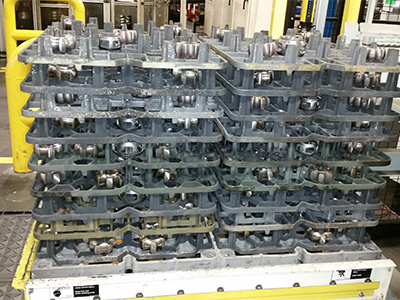
Figure 2: 2015 – Alloy Fixture: 1000 x 610 x 660 mm
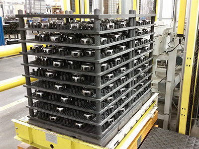
Figure 3: 2015 – CFC Fixture: 1000 x 610 x 810 mm
To complete the evaluation of LPC on the cage, an estimation of the size of the heat treat installation and the cost per load of cage has been simulated. These are based on an annual production (245 days per year) for two models of cages (smallest and largest), which add up to about half a million of each part. The load size is based on the model of ICBP that Nexteer had purchased: 1000 x 610 x 900 mm. The weight of the load was guessed between 500 and 525 Kg. The quantity of cages per load was calculated for 660 parts for the largest model and 1250 parts for the smallest using the best fixture configuration. With a cycle time of 4 hours and 30 minutes per load included heating up, carburizing, austenitizing, and an uptime of the installation at 85% after start up and maintenance; a 9 heating cell ICBP is necessary. With this furnace, Nexteer could run 41 loads per day for a cost of $29 to $30 per load, this price is relative to the use of the ICBP only, the other cost elements of the heat treatment process like external handling, washing, pre-oxidation and tempering ovens were not included. When calculating the cost, we set the price of electricity at .00825 $/KWh, the acetylene at 0.1 $/f³ and the nitrogen at .0032 $/f³. The breakdown of the cost calculated per cage is 90% for the electricity, 7% for the process gas and 3% for the nitrogen included in the gas quenching under nitrogen. If the price is reported to a price per cage, the heat treatment of LPC for the small part will be about 2.5 cents and 4.5 cents for the large one. Nexteer has estimated their cost per cage into their atmosphere carburizer at around 29 cents. The difference of cost may come from the different prices of utilities and cycle time of the heat treatment.
EVALUATION OF SAMPLES
Metallurgical properties of parts that have been previously mentioned throughout this paper were analyzed. The following describes how each sample was tested. Once the parts were low pressure vacuum carburized, high pressure gas (nitrogen) quenched and tempered, a sample from each development load was tested initially for typical metallurgical parameters including surface hardness, core hardness, effective case depth, total case depth and microstructure. Once it was established through metallurgical results that the 2015 alloy fixture LPC parts were comparable to that of the current atmosphere carburizing parts, samples were then product tested in the form of fatigue strength performance. The parts were made into outer race assemblies and ran in a test fixture to specific customer requirements in order to meet a pass or fail criteria. Once the parts passed, the test was continued until the part fractured to determine if the LPC cage and atmosphere carburizing cage would fracture in a similar manner.

Macro fractography was then performed using a stereoscope to determine the fracture origin and mechanism of fracture. Micro scale observations via a scanning electron microscope (SEM) using an accelerating voltage of 20kV and various magnifications were also done. A transverse section of each part was cut using a wet cutoff saw, and then sanded using four steps with 240, 320, 400 and 600 grit SiC paper. This cut was as close as possible to the fracture origin (and in approximately the same location on the not product tested parts from the 2008 and CFC fixture trials). The samples were then polished using a diamond-polishing compound with a size of 6μm followed by 1μm. The polished samples were used to evaluate hardness and case depth via microhardness testing with a 500g load using the Vickers Scale. A microhardness traverse was started at the outer diameter of the part as close as possible to the fracture origin and completed at approximately half way through the wall thickness at 2.0mm (essentially the core of the part) using increments of 0.1mm. Lastly, each polished sample was then optically evaluated using an inverted light microscope both in the un-etched and etched (2% nital etchant) states so that the amount of intergranular oxidation (IGO) and microstructure could be compared. The part distortion was also measured using a Zeiss metrology system to accurately measure smaller parts, like the cage.
SUMMARY OF RESULTS
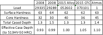
LPC with a high pressure gas quench metallurgical results were considered optimal when they became comparable to the current production atmosphere carburizing with an oil quench process since that has been the bench mark heat treatment for the part since its initial design. The surface hardness, core hardness, effective case depth, total case depth and microstructure were all considered.
As seen in Table 1, the initial results in 2008 did not compare to the benchmark process in core hardness; however, all other parameters are considered equivalent. This is also seen on Graph 1, which compares all trials’ microhardness case depth data. There is a slight difference in the transition from the surface to core of the LPC and atmosphere carburized samples. The parts tested from the 2015 alloy are considered optimal since they are comparable for all metallurgical aspects, including core hardness.
Also, the parts from the 2015 alloy fixture are equivalent to the atmosphere carburizing in that they all passed product performance requirements. Additionally, the cages both through the LPC with gas quench and atmosphere carburizing with oil quench had very similar fracture mechanisms and origins (Figures 4 through 6). Both samples initiated fracture due to high load fatigue with a final fracture from an overload. Scanning electron microscopy showed the vacuum carburized fracture origin was mainly transgranular, which was very similar to the atmosphere carburized cage. However, the atmosphere cage showed almost completely transgranular fracture morphology at the origin, which is indicative of a high load fatigue.
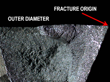
Figure 4: Representative macro photograph of fracture morphology and origin for both atmosphere carburizing and LPC cage samples.
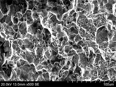
Figure 5: Fracture origin of LPC cage showing mainly transgranular fracture morphology resulting from a high load fatigue type fracture

Figure 6: Fracture origin of the atmosphere carburized cage showing almost completely transgranular fracture morphology
The microstructure in the area of the fracture origin was also very similar for both samples. The outer diameter consists of tempered martensite and the core has varying amounts of bainite. Since the fracture origin occurred at the outer diameter corner refer to Figures 7 and 8 for comparison micrographs. The vacuum carburized sample does have a slightly coarser grain size than that of atmosphere carburizer. This may be due to the higher temperature of the LPC and that the material used was developed for an atmosphere carburizer with an oil quench system.
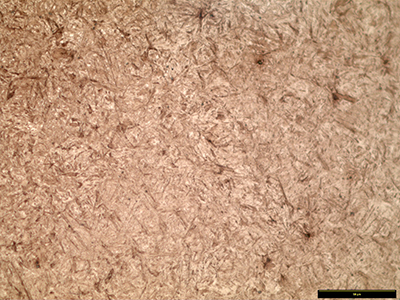
Figure 7: Photomicrograph in the fracture origin area of the LPC cage exhibiting tempered martensite (500X magnification)
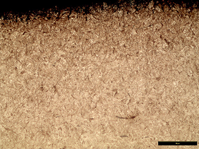
Figure 8: Photomicrograph in the fracture origin area of the atmosphere carburized cage exhibiting tempered martensite (500X magnification)

Figure 9: Intergranular oxidation from the inner diameter surface of the atmosphere carburized cage (1000X magnification)
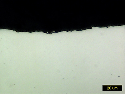
Figure 10: Un-etched micro of the LPC cage sample showing no IGO (1000X magnification)